In 2021, our company has relentlessly push the limits of our engineering to deliver even better products for our customers.
2022. Better MAX.
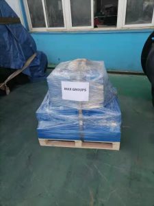
It doesn’t matter how small
or big the order is, MAX team is committed to only shipping great products.
R&D
As always, our R&D team is constantly working on finding ways to lower costs for our customers while maintaining the high quality of our products that pass our stringent internal controls.
Throughout the year our Research & Development (R&D) team have experimented with raw materials
and even worked with improving our logistics procedures to minimise waste and maximising efficiency.
MAX products to India, Malaysia, Singapore, Indonesia, Australia, France, USA and more!
This past year (2021) we have continued our tradition to delivered to various continents our rubber fenders, marine airbags, as well as floating discharge hoses.
In 2021 alone, we shipped to countries in Europe, North America and of course, many parts of Asia!
Last but not least, Happy New Year!
In view of the COVID-19 situation world-wide, we sincerely hope all our suppliers, customers, friends and family stay safe!
Please have a great 2022 and Lunar New Year!
May the year be filled with more blessings and prosperity while our team continues to serve you in your marine airbag, rubber fender, marine winch, rubber hoses, & more marine equipment needs!
To all our customers, colleagues, partners, friends and families, everyone of us at MAX wishes all a year of happiness, prosperity and good health ahead.
Happy New Year 2020!!
And for those celebrating, Chinese New Year is around the corner too! Let’s have an even better Year of the Rat! Gong Xi Fa Cai in advance!
Our factories and offices will be closed during 23/1/2020 until 12/2/2020, with some of our colleagues taking more leave, so we hope you bear with us if we are a little slow in replying.
A big part of MAX’s business also manages and advises shipyards in launching or ship repair processes. These days, for trickier projects with challenging ship dimensions or special situational slipways, our team uses 3D printing to help with our demo.
3D printing is very commonly referred to as additive manufacturing. It is when successive layers of material (for our use, it’s PLA) are slowly laid down under precise intelligent control to form a 3D shaped object. 3D printers is a rising trend of rapid prototyping in today’s world. For MAX, we use it to make demo kits according to precise specifications of our clients’ vessels.
Unlike our old presentation, now for certain cases, our presentation and discussion features a more lively demo with 3D printed objects scaled down (usually 1:500) according to exact dimensions of our clients’ modules. Besides, this also enabled our team to understand the dimensions of the module more clearly with a physical object in hand. It certainly helps our customers understand better and have a look of a scaled down ratio of things
3D Designing, Rendering & Slicing for Print
Our team studies the dimensions or require clients to send their designs so that we can proceed with slicing for printing preparation. At this stage, the amount of time, materials and configurations are carefully considered. (Due to the confidentiality of the designs, we are unable to showcase photos for real projects).
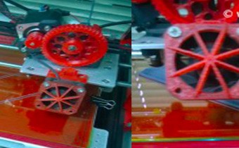
Printing a Demo Kit
The printing process ranges from a couple of minutes up to 20 hours! It mainly depends on printing quality, speed & configurations.
3D printing is adopted in our sales & marketing team as we hope to establish effective communication with our stakeholders. MAX is proud to be embracing new technologies like we always have to improve our delivery to clients. This is especially true at the time where we are popularising an extremely versatile ship launching method worldwide especially in America, Europe and South East Asia. Learn more at Shiplaunching.org.
The Ultimate Guide to Ship Launch, Ship Repair & Marine Salvage using MAX Air Bags
MAX Marine Airbag technology is an extremely flexible technology where it can handle heavy structure launchings (ships, boats, floating jetties, caissons), ship repair haul-ins and marine salvaging cases.
While we cannot disclose the details of calculation due to professional competitive advantage, this guide aims to give an overall view of how MAX advises our clients.
MAX Rubber Airbags are really cost-effective in launching a vessel.
They are very suitable even for smaller-sized barges to tug boats up to bigger-sized chemical tankers and containerships.
However, it is very important to understand that rubber airbag launching is not a ‘one-size-fits-all’ method.
Marine rubber air bag launching is not a ‘one-size-fits-call’ method. Tweet this!
In fact, MAX team would need to understand all the necessary technical specifications of the vessel (or structure, as this launching method can also be used to launch caissons & floating jetties etc) and many external factors.
The first step is to identify the vessel size & dimensions.
Identify Main Dimensions & Types of Vessel
At MAX, we believe in listening before we jump to conclusions and putting our clients priorities first.
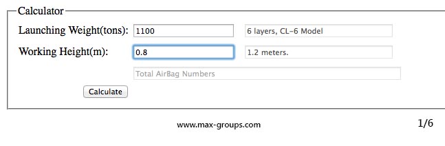
Before proceeding in advising, MAX staff would normally request our prospects to fill in a technical specifications form.
Factors like:
Length overall (L.O.A.),
Beam,
Draft,
Launching weight (light weight) of the vessel
Working height (distance between ground and the hull of the vessel), are just a few crucial things we need to know.
This enables our team to understand the weight dynamics of the structure during launching.
Equally as important, we also ask for a GA plan as the main ship design different designs of the structure plays a role in choosing an efficient air bag solution.
Selection of MAX Marine Airbag
After understanding the type of vessel and its principal dimensions, MAX staff is then able to recommend the:
Types
Sizes
Numbers of airbags.
A weight allowance of a certain percentage of the vessel weight is taken into consideration.
This helps MAX to ensure a safe launching process by not overexerting the rubber airbags and also have a safety margin, should there be any additional weight carried by the vessel during launching.
It is important to take into consideration a safety factor of weight allowance during selection of marine air bags. Tweet this!
Based on the dimensions and structural design, the team can recommend the dimensions of the airbag in terms of length, diameter and type.
Then, based on calculations and careful projections, MAX staff is able to determine the guaranteed bearing capacity per airbag.
At this point, extra airbags for launchway mobilisation will be included in our recommendations.
The selection process of MAX airbags is also checked by our MAX Smart Ship launching software.
Due to professional competitive advantage, this is a screenshot of just a part of the software.
This software is developed by MAX software engineering team and acs as a double-checking process to enable a safe recommendation of the optimum number and types of airbags for use.
General Ground Structure Preparation
MAX airbag launching process requires a hard ground so that the whole structure will not sink during launching.
If the ground consists of sand or is soft, there are many options that our staff will recommend.
MAX also helped many of our clients prepare concrete ground as launching slipway for airbag use.
This would require a very delicate study of the nature of the ground and in-depth analysis on a case-to-case basis. Thus, it is crucial that this aspect should not be overlooked.
Pulling force plays an especially huge role for certain launching projects that require a slow and steady launch approach, needing the winch to be able to operate long periods of time.
Placing of Rubber Airbags
MAX team uses 3D projections to determine the placement of rubber airbags at ready-launch position.
This helped give a 3D view on how to evenly distribute the weight of the vessel/structure for maximum safety.
MAX takes into careful consideration the distance between components and how to coordinate the metal strut/stand locations.
With its advantages, launching of structures up to 10,000 Tonnes using this method is pretty common these days.
It is widely acknowledged that our quality launching bags are able to be used up to more than 5 years and is very cost efficient compared to most traditional launching methods.
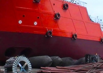
This is a simple breakdown of the common air bag launching process.
It started with a winch holding the vessel in place.
Airbags are placed underneath the ship’s hull.
Air bags are then inflated.
The transfer of weight from support blocks to having the airbags actually lifting the vessel itself.
Remove the support blocks.
Then the winch’s pulling force is slowly decreased to enable mobilisation of vessel towards the sea line.
At a certain point, the connection between winch and vessel will be released using MAX quick release shackle.
The vessel, assisted by gravity and launching bags, will be launched safely into the sea with minimal risk.
Please note that however, there are many different scenarios to cater to different situations and different vessels, so this is just an overall idea of it.
View a Youtube video of the launching of Sealink Asia 101 by MAX below:
Ship Repair Section
Like the ship launching method, the main concept and preparation process are both very similar, just reverse the process. Please go through ship launching section first before reading this section to better grasp the idea.
Most calculations are inverted and the core concept of having strong enough pulling force (in this case, hauling winch) is key to maintaining a steady hauling process for ship repair.
Understanding Principal Dimensions & Weight of Vessel
Similarly to the vessel launching process, the hauling in of vessel for repair projects require MAX to analyse its dimensions in detail.
Weight, overall ship length and width are some of the aspects MAX engineering team would take under consideration.
The design of hull and ship has to be considered as well for hauling process as structural differences can affect the types of airbags used.
Choosing Suitable MAX Airbags
Main dimensions and structural design of the vessel helps MAX team to recommend the dimensions, thickness, specs & number of air bags needed.
When choosing the most suitable bags for hauling use, safety is our number one priority.
Marine bags should not be overexerted.
That is why MAX’s experienced technicians will add a percentage of weight contingency in calculations.
This will add a ‘safety cushion‘ also to accommodate any excess weight that the vessel may have added.
Next, detailed projections and careful calculations enable MAX to identify the bearing capacity per airbag.
This figure is subsequently used to deduce the total number of bags needed, including extra bags for launchway mobilisation.
MAX team will then use our in-house developed MAX Smart Ship Launching software to double-check the calculations.
Pulling Winch / Hauling Winch with Enough Pulling Force
Depending on the angle of the slope, the dimensions & size of vessel, a winch and the entire pulley system will be recommended to provide sufficient pulling force.
Ship Repair using Launching Airbags
Most of the process is similar to the airbag ship launching process.
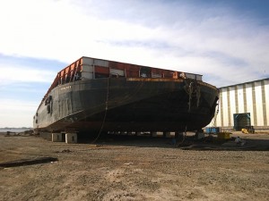
Instead of launching the vessel into the water, rubber airbags help lift the vessel out of the water, supporting its movement towards land using the winch’s pulling force.
This innovative product helps boost a yard’s ship repair capacity without needing to invest in building another dry dock.
A hard ground is sufficient to enable vessel hauling using airbags, and repair works can be performed at the same location.
The entire hauling process is a delicate case-to-case situation.
MAX’s experience and detailed projections will ensure you a safe ship haul-out process.
Marine Salvage is the process/project of recovering a vessel (ship), its cargo, or items after a ship wreck.
This includes towing of a vessel, patching of a ship or re-floating a sunken/grounded ship.
MAX Airbags is a popular product for re-floating a sunken/grounded ship.
Marine salvage using rubber bags are mainly case-to-case studies where MAX technical team will advise only based on known data.
Here is just a general idea of how MAX would assist in vessel salvaging projects:
Buoyancy Needed to Re-float Vessel
The in-depth study & calculations of buoyancy needed will be carried out by MAX.
With this, MAX is able to advise on the size and type of MAX salvaging bags (There are custom made and very different when compared to launching bags with more emphasis on floating ability etc).
Depth or Water Pressure
MAX needs to understand the scale of the project and the magnitude of it to determine the strength & type of mobilisation/re-floating airbags.
We have worked closely with marine salvaging teams in many parts of the world since Hurricane Katrina in 2005.
Our experience in these projects would ensure the success of your marine salvage projects.
So if you’re a marine salvaging team, contact us for high quality and reasonably-priced MAX rubber airbags.
Launching a ship is the most important process in ship construction. It not done right, it erases all the hard work building the ship itself. Sometimes, people take ship launching for granted and it came as no surprise that many ship launching projects fail due to negligence.
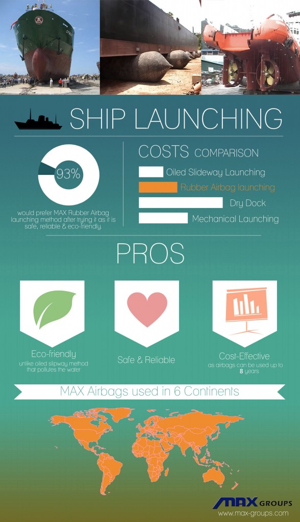
A table for some of the most popular ship launching method comparisons:
METHOD
COST
SAFETY
ENVIRONMENT
Oiled Slideway Launching
(Longitudinal & Side)
Low costs.
Dangerous as front part of the ship undergoes huge pressure. The immediate drop into water also might cause collision with the bottom of the river/sea. Many accidents happen for especially side ship launching.
Oil used will pollute the water.
Roller Slideway Launching
Initial installation costs are high.
Moderate.
Eco-Friendly
MAX Ship Launching Airbags
Very cost-effective. Ship launching airbags can be re-used many times & usually has a lifespan of 5-8 years.
Safe. MAX Ship launching airbags provide support to the hull of the ship and aids its launching motion into the water.
Eco-Friendly
Dry Dock Floating-Out Launching
Initial investment is extremely high.
Safe.
Eco-friendly
Mechanical Type Launching
(With mechanical features)
The construction and maintenance for mechanical features are extremely high.
Risky, and only for smaller vessels. You can see many accidents happen for this type of ship launching.
Eco-friendly
If you are still using oiled slideway ship launching, it may be time to consider a more eco-friendly and safe ship launching method.
If you are launching your ship with dry dock float-out method, consider whether it is necessary for such a huge initial investment for your vessel. The float-out method is great for massive ships (more than 15,000DWT ships) but for ships with a DWT of less than 10,000 tonnes, ship launching airbags can help launch the vessel with relative ease. For those more than 10,000 tonne DWT ship launches, careful projection and a professional team’s assistance may be required. Still, it is usually much more cost-effective than dry dock ship launching. Rubber air bag vessel launching is a much preferred option especially popular in South East Asia, though it is already picking up momentum in many other regions like Europe and North America.
Airbag Ship Launching. Cheaper than dry dock launching, more eco-friendly than oiled slipway launching. Tweet this!
Do you experience a short lifespan for your marine products like ship launching airbags? Deal with a supplier who is slow in responding and service? Or did you pay extremely high prices for an average quality product that often fails you? 83% of our global clients claim that these are the problems that made them search for a better alternative and subsequently worked with us since.
MAX is known for our products’ great quality-to-price ratio andresponsive customer service. Moreover, from our global sales office to manufacturing plants, we are committed to ‘Go Green‘ for the environment. Drop us an email and we will assist!
Here’s what makes our airbags special:
MAX Groups Marine has launched various types of vessels in 6 continents using marine airbag technology. For more info of our projects, visit <http://max-groups.com/projects/>
MAX Marine Airbag technology is a flexible technology where it can handle heavy structure launchings (ships, boats, floating jetties, caissons), ship repair haul-ins and marine salvaging cases…[Read More]
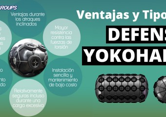
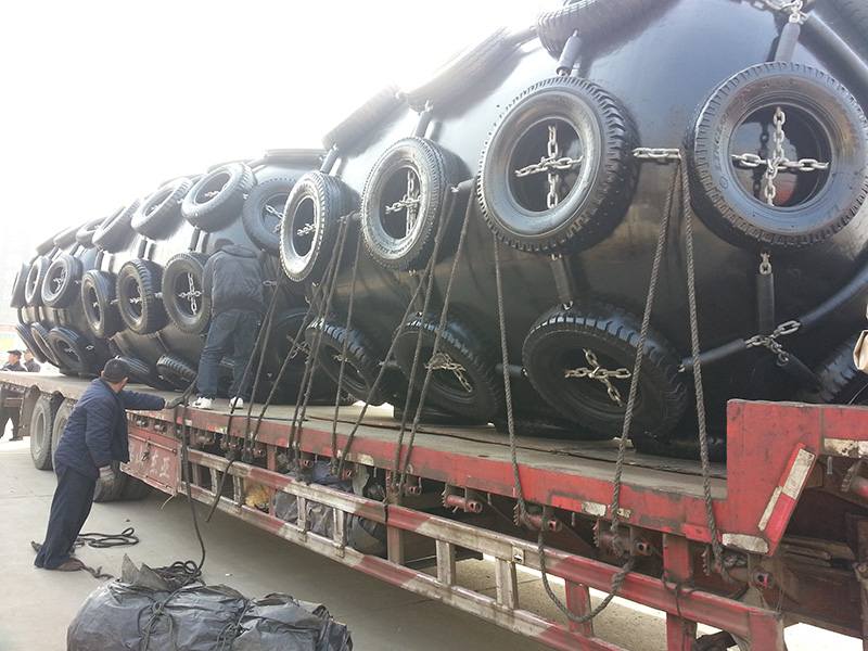
Defensas Neumáticas Flotantes de goma, tipo Yokohama
Las defensas neumáticas flotantes de caucho son consideradas como uno de los principales equipos anticolisiones para las aplicaciones marinas. De acuerdo con la norma ISO 17357: 2002, las defensas neumáticas flotantes de goma en ocasiones son denominadas de forma coloquial como “defensas Yokohama” o “defensas tipo Yokohama”.
Juegan un rol activo como medio de protección contra las colisiones en las operaciones de contacto de barco a barco y de barco a embarcadero. Su mayor ventaja es que absorben una gran cantidad de energía, con baja presión en superficie de la unidad sobre barco. También se utilizan como defensas de emergencia, en buques petroleros, gaseros y barcos de carga a granel.
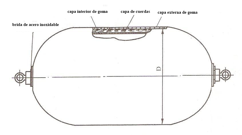
Composición
La composición básica de las defensas neumáticas de caucho consiste en una capa externa de goma, capas de cuerdas y una capa interior de caucho vulcanizadas juntas. Las bridas de los extremos están disponibles en ambos extremos para propósitos de carga. La capa de goma externa está hecha de material de caucho fuerte para resistir fuerzas externas y proteger a las otras capas de la abrasión, así como para uso rudo en malas condiciones meteorológicas. Las capas de cuerdas están diseñadas de forma innovadora en ángulos ideales para distribuir uniformemente la tensión que actúa sobre la defensa. Se aplican tanto la tecnología de entramado de cuerdas como la fibra de poliamida de alta resistencia a la tensión para proporcionar resistencia y mantener la presión interna durante el uso. Esto ayuda a distribuir uniformemente la tensión, manteniendo la absorción de energía y aumentando su eficiencia. La capa interior tiene la tarea de sellar el aire que se encuentra dentro, reduciendo al mínimo las fugas de aire ya que utiliza un material con cualidades herméticas.
Principales tipos de redes protectoras
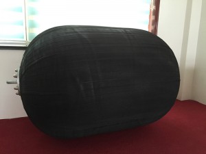
Las defensas neumáticas pueden venir sin red de protección y generalmente son de color negro. Los colores se pueden variar según las necesidades del cliente y suelen tener 3 tipos de redes de protección para mejorar la vida útil de los productos.
(i) Red de cadenas de neumáticos
(ii) Red de alambre de caucho
(iii) Red de fibra
Ventajas de las defensas neumáticas
(Clic para agrandar)
Hay varias razones por las que las defensas neumáticas marinas son la opción preferida para muchos.
Ventajas durante los atraques inclinados
Durante el atraque, el contacto inicial con el muelle suele tener un ángulo oblicuo y pone mucha presión en ambas superficies (la del muelle y la del barco).
En las típicas defensas de goma sólidas, al tener una compresión inclinada, la absorción de la energía disminuye considerablemente. Por lo tanto, no son poco comunes las situaciones en las que las personas optan por defensas sólidas de mayor tamaño. Por otro lado, la tasa de absorción de energía de las defensas neumáticas se mantiene en un nivel superior incluso cuando las comprimen en determinados ángulos. Debido a una distribución más uniforme de la presión de carga, el rendimiento del par de torsión contra el muelle suele ser menor en comparación con los diseños convencionales de los sistemas de las defensas sólidas.
Mayor resistencia contra las fuerzas de torsión
Al hacer contacto con el muelle, los barcos son por lo general movidos lentamente a una posición óptima de amarre. Esta acción ejerce una gran fuerza de cizallamiento y compresión en la superficie de las defensas. La mayoría de las defensas sólidas están severamente dañadas a causa de estas fuerzas ya que no están diseñadas para resistir intensas fuerzas de cizallamiento y fricción. Ese es el motivo por el que la mayoría de las defensas marinas tienen paneles frontales para hacer frente a este problema y proteger las defensas de goma de las fuerzas directas de cizallamiento. De esta forma, las defensas no entran directamente en contacto con el barco. A diferencia de las defensas de normales, las defensas Yokohama pueden resistir altas fuerzas de cizallamiento desde todos los ángulos gracias a sus propiedades neumáticas (llenas de aire). Esto las convierte en una alternativa ideal en comparación con las voluminosas dimensiones de los marcos de las defensas frontales.
Son relativamente seguras incluso durante una carga excesiva
En general, todas las defensas deben utilizarse dentro del impacto del límite de carga. Sin embargo, en situaciones de la vida real, es común ver que las defensas suelen recibir exceso de cargas accidentalmente. Cuando eso sucede, lo fantástico de las defensas Yokohama es que la fuerza de reacción no aumenta considerablemente bajo una carga excesiva. En contraste, las fuerzas de reacción de las defensas sólidas tienden a subir marcadamente bajo condiciones de carga excesiva y dañan la nave durante el proceso de amarre. Las características de las defensas neumáticas flotantes también contribuyen al proceso ya que permiten una distribución más uniforme de la tensión.
Ventajas durante condiciones climáticas cruciales
Durante condiciones climáticas cruciales, cuando la acción de las olas es intensa, los procesos de amarre se complican aún más debido a la acción desequilibrada de movimientos hacia arriba y hacia abajo en el muelle. Esto ejerce una fuerza de torsión más alta en las defensas y el cambio de frecuencia en las fuerzas durante el amarre en tales condiciones meteorológicas ocasionará fatiga en las típicas defensas de tipo sólido. Sin embargo, por otro lado, el área de contacto flexible de las defensas Yokohama, así como sus amplias características de deflexión permisible minimizan la fatiga durante dichas situaciones. Debido a que las defensas son defensas flotantes, su rendimiento de absorción de energía se ve menos afectado por las diferencias severas en las olas de la marea. Para mares con situaciones difíciles o con frecuentes condiciones meteorológicas adversas, así como fuertes diferencias en la marea, las defensas neumáticas flotantes marinas de caucho pueden ser una mejor opción ya que suelen mostrar una vida más larga.
Deterioro en el rendimiento minimizado
El envejecimiento y la fatiga causan frecuentemente que las defensas se deterioren en términos de rendimiento. Sin embargo, debido a su composición llena de aire y que son altamente elásticas, estos problemas se reducen al mínimo. Las defensas de caucho sólidas o las defensas de espuma dependen más de la dureza del material, y dicha dependencia puede resultar en la disminución del rendimiento de absorción de energía y en cambio de temperatura después de años de uso. Por otro lado, siempre y cuando se les de mantenimiento básico y control de la presión del aire, las defensas neumáticas se desempeñarán con un rendimiento óptimo a temperaturas extremadamente bajas de hasta -50 grados Celsius, o incluso durante fluctuaciones de temperaturas altas.
Adaptación a la marea
Las defensas Yokohama son principalmente del tipo flotante, lo que significa que las defensas flotan en el agua en un plano vertical sin restricciones a la amplitud de la marea y al movimiento vertical del barco. Por lo tanto, la absorción de la energía de las defensas siempre sucede en la posición más óptima.
Instalación sencilla y mantenimiento de bajo costo
Las defensas neumáticas pueden instalarse simplemente por medio de cuerdas o cadenas a un costo adicional mínimo. En este tipo de defensas flotantes, la transferencia o remoción también es muy flexible y fácil. El mantenimiento de las defensas neumáticas (defensas tipoYokohama) incluye revisiones anuales sobre la presión interna del aire, inspección de las condiciones físicas de la red de la cadena y de la superficie de la defensa. Por lo general, las redes de las cadenas tienen una vida útil de aproximadamente 3 a 4 años, dependiendo de su uso.
Para aprender más sobre las defensas neumáticas flotantes de caucho, visite nuestra página del producto ‘Pneumatic Fender‘.
This article post aim to discuss the generally used equations, formulas, factors to determine a suitable port fender design. All formulas and equations are only intended as reference only. If you have a project, drop us an email so our technical staff can advise you.
Contributed by Wang.
A solution to absorb collision & prevent damage
Since the early days of floating crafts & small wooden boats, fenders were woven from ropes to absorb collision during berthings. Similar to the products we have today, they came in various sizes and patterns to serve different needs. The primary function of such a “soft-contact” system is to prevent the vessel from sustaining damage as the ship or boat is being moored against the quay wall. However, the vast amount of variations may confuse some looking to purchase certain fenders for their new-built port or jetty. In short, impact forces during the vessel berth, abrasive action, among other factors must be taken into consideration as well as the block safety coefficient to provide some allowance. The multi dimensional forces may cause extensive damage to the jetty structure AND the ship at the same time if a less suitable fender is used (or worse, a low performance fender system is deployed). So, it is about absorbing contact and distributing the force onto a larger surface area to prevent damage. Aside from mostly uniformly distributing collision force, it also increases impact time to lower the reaction force in whole.
Yes, it is important to have a structure of this kind to prevent damage to the quay wall or jetty or harbour.
Quite simply, determining a suitable marine fender system comes down to considering:
Amount of Energy Absorbed and Maximum Impact Force Imparted
Common Selection Process: All Conditions must be Carefully Studied
It is important to keep in mind that the local marine condition is as big a factor as the ships the quay is accomodating. Both aspects affect the choice of “marine bumpers” used. So it is not surprising to see two different types of fender systems being deployed in the same city, but to accommodate different types of ships. Harbor conditions are also rarely the same. Successful previous local experience must be considered. The best way to figure out what type of port fender is suitable for your berthing structure would be to carefully study your own local marine condition that includes:
Site condition and depth
Local temperature range & weather
Wind velocity
Direction of ship when berthing
Tidal range & wave height
Berthing structure
Type of ships, along with class, configuration, size
Velocity of ship approaching the quay wall during berthing
Exposure of harbor basins
Available docking assistance
Before diving into this guide, one has to understand that the design criteria differ from one person to another. So this article is aimed to act as jsut a reference for many. For detailed project designing & fender choosing, kindly contact a professional team to design suitable marine fender system.
Prior to designing and doing any calculations, one has to prioritise one’s design standard and criteria.
Are there any specific codes and standards that you need to conform to?
Intended useful life of product? Some fenders are longer lasting than others.
Safety factor?
Designated vessels for berthing calculations?
Velocity range?
Costs: From installation fees, to maintenance costs. All has to be thoroughly considered.
Guide:
The law of energy conversation is the basis for all fender design selection. When choosing fenders, it is vital to base calculations and considerations on the largest (heaviest) vessel sizes to be berthed at the wharf. Besides, vessels are getting larger as ship design evolves from time to time. It is important to take into consideration those expected to arrive in the near foreseeable future.
Fender Energy Absorption = Energy Delivered upon impact – Energy absorbed by pier
To understand how much energy absorption is needed, one needs to first determine the energy that will be delivered to the quay wall upon initial impact.
Secondly, one has to then carry out calculation to find out the energy that requires to be absorbed. For linearly elastic structures, the energy is ½ the maximum static load level times amount of deflection. Some allowance should be added. If the structure is very rigid, one can assume no energy absorption from the pier.
Minus the energy amount absorbed by pier and one can determine the fender energy absorption value that is required for a safe berth.
Then, one can choose a suitable fender type and design from a wide range of available marine fenders in the market today: from super cone type, arch type, cylindrical shaped, to floating types like Yokohama fenders and foam fenders. Be sure to select a manufacturer that adheres to PIANC2002 and/or other standards to ensure great quality fender products.
GT
Gross Tonnage
Total volume of cargo + vessel
NT
Net Tonnage
Total volume of cargo on vessel
DPT
Displacement Tonnage
Total weight of the cargo-filled vessel when vessel is loaded to the draft line
DWT
DeadWeight Tonnage
Weight of cargo + people (including crew) + fuel + food on the vessel
LOW
Light Weight
Vessel weight
BW
Ballast Weight
Weight of the vessel when water is added in the ballast
Types of Berthing Approach:
Side Berthing:
‘Dolphin’ Berthing:
End Berthing:
Lock Entrances:
Ship-to-ship (STS) Approach:
This article only discusses berthing calculations for side berthing. If you have a Ship-to-ship (STS) operation or End Berthing, certain equations may be different. Contact our team for assistance.
Effective Berthing Energy formula for Side Berthing:
This is the most common berthing method for docks. The berthing energy is calculated with the equation:
VB = Berthing velocity of the vessel at the moment of impact (m/sec, ft/sec). Berthing velocity is an important parameter in fender system design. It depends on the size of the vessel, loading condition, port structure, and the difficulty of the approach. The most appropriate method to determine berthing velocity is based on actual previous statistical data. If that is not possible, the most widely used reference would be the Brolsma table, adopted by BSI, PIANC and other standards. However, it is important to keep in mind that the best option is still to base on previous statistical information.
CM = Mass Coefficient/Virtual mass factor: During the sudden stop of movement as a vessel comes into contact with the berth, the mass of water moving with the vessel adds to the energy acting upon the vessel and fender. This situation is referred to as “Added Mass Coefficient” or “Mass Factor”. Weight of water moving that adds to that is called “ Additional Weight” in these berthing studies.
As the vessel is stopped by the fenders, the momentum of the water continues to push against the vessel and this actually increases its overall mass, so CM has to be calculated. There are 2 ways to calculate its mass coefficient.
The most commonly used “Vasco Costa (1964) method”:
CE = Eccentricity factor. The reaction force will give a rotational movement at the moment of contact. This will dissipate an amount of the energy. There are 2 formulas to determine the eccentricity factor:
You require these info:
Distance between center of mass (vessel’s) to the point of impact (R)
Velocity vector angle (v)
Radius of gyration (K)
Berthing angle(α)
NOTE:
K: Radius of vessel rotation (usually 1/4 of the vessel’s length)
R: Distance of the line paralleled to wharf from the vessel’s Center of Gravity (CG) to the contact point. Common cases are 1/4 to 1/5 of vessel’s length.
CB: Block Coefficient, which is related to the hull shape.
WD:Water displacement of the berthing ship(kg, Tons, lbs)
: Sea Water density(1.025 Tons/m3)
LBP: Length between perpendiculars. Please see sketch below for better explanation:
x: Distance from bow to point of impact
B: Beam(m, ft)
Formula (i): The more detailed calculation to find out CE :
If the beam, length and draft information are not available, this table can be used to estimate:
Typical Block Coefficients(CB)
Type of Vessel
CB BS 6349
CB PIANC 2002
Tankers
0.72~0.85
0.85
Bullk Carriers
0.72~0.85
0.72~0.85
Container Ships
0.65~0.75
0.60~0.80
General Cargo
0.60~0.75
0.72~0.85
RoRo Vessels
0.65~0.70
0.70~0.80
Ferries
0.50~0.65
0.55~0.65
Formula (ii): The more simple formula to find out CE :
This method can lead to a serious underestimation of Berthing Energy when the berthing angle (α) is greater than 10° and/or the point of impact is aft of quarter-point(x > LBP/4).
To verify your calculations, one can check the calculated C E values to ensure they generally fall within the following limits:
CC = Berth configuration factor. This is the part of berthing energy absorbed by the cushion effect of water between the approaching vessel and the quay wall. The smaller the draft (D) of the vessel is, or the larger the under keel clearance(KC), the more trapped water can escape under the vessel, and would give a higher CC value. Also, if the berthing angle of the vessel is greater than 5°, we can consider CC = 1. Different dock types would have different variations.
Closed Dock case
A closed Dock would be a wharf, where you have a concrete wall going directly to the sea ground. In this case the quay wall will push back all the water that is being moved by the vessel. This creates a resistance factor that can be calculated as follows:
If KC ≤ D / 2, CC ≈ 0.8
If KC > D / 2, CC ≈ 0.9
Open / Semi-Closed Dock case A semi-closed dock is when water can flow underneath the dock, but the depth changes below the dock. Open dock is usually a dock with piles underneath and the water can flow freely underneath the dock. In such case we can assume the following value of 1.
CS = Softness factor. This is the energy absorbed by the deformation of the vessel’s hull and fender. Usually, we can assume CS ≈ 0.9.
When selecting the size of fenders, it should be selected base on the consideration of kinetic energy of contact between two vessels or between vessel and berthing facilities may be absorbed by a single fender. The following tables are given for determining the energy absorption depends on approaching velocities for various ships.
Energy absorption for ship-to-Jetty (for reference only)
Table (viii) Energy Absorption of Ferry Boats at ¼ point Berthing (KJ)
G/T
Assumed Weight (t)
Approaching velocity ( m/s )
0.20
0.25
0.30
0.35
0.40
0.50
0.60
50
124
1.3
2.0
2.8
3.8
5.1
7.9
11.0
100
246
2.5
3.9
5.6
7.7
10.0
16.0
23.0
200
430
4.4
6.9
9.9
13.0
18.0
27.0
39.0
300
664
6.8
11.0
15.0
21.0
27.0
42.0
61.0
500
1,012
10.0
16.0
23.0
32.0
41.0
65.0
93.0
1,000
1,796
18.0
29.0
41.0
56.0
73.0
115
165
After having the effective berthing energy value, one can then choose the suitable type of marine fender design / system. Performance has to be compared in order to design the most suitable system. For example, deflection curve, energy absorption and reaction of a cylindrical fender is different from an arch-shaped fender. One has to compare alternatives and then determine which one is more suitable for use. This is when previous records of fender systems deployed play a big role in advising the suitability for the particular marine condition.
Energy Absorption:
The obvious factor in designing a fender system. This value has to be higher than the effective impacting energy of ships.
Reaction Force:
This value has to be less than the vessel’s allowable reaction force to prevent damage to the hull surface (or in extreme cases, the structure as a whole).
Environmental Condition:
It is vital to determine how harsh the working conditions for the fenders will be. One will have to choose accordingly its durability to handle strong waves, winds, or extreme weather. If the working condition is very demanding, it is possible you will have to replace the fenders quite often.
Berthing Angle:
A fender that can accept a situation’s angular compression has to be considered. An angular compression does not result in a simplistic linear energy absorption curve so this has to be a main priority when choosing a rubber fender design.
Fender (or Panel) Surface Pressure
Surface pressure value of fender has to be less than the vessel’s allowable hull surface pressure. For certain fenders like super cell type and cone type, they most commonly come with frontal frames/panels that distributes the pressure. So to decrease surface pressure value, one can increase the surface area of the panel.
Trustworthy Supplier
Choose a quality rubber fender manufacturer. Some people always assume that prices and quality can not come together but it is possible in today’s manufacturing innovation and high tech automation processes. Manufacturers are spending less time doing low importance repetitive work and focusing on Quality Control (QC) processes assisted by great process flow.
Fender Arrangement and Spacing In Between
After choosing what type and size of fenders to use, the next step is determining the number of fenders. To do that, one has to take into consideration fender spacing. The spacing between fenders play a very important role in determining a fender system’s success. Should one opt to save cost and have too great a spacing between fenders, accidents might happen where vessel berthing might hit the dock structure. British Standards recommend that for a continuous quay, the installation pitch is recommended to be less than 15% of the vessel.
The maximum spacing between fenders (S) can be calculated with this equation:
Maximum Spacing between Fenders,
Note:
RB = Bow Radius of Board Side of Vessel (m, ft).
If radius info is not available, one can use this estimation to find out the info:
PU = Uncompressed Height of Fender incl. Panel (m, ft)
C = Fender Height in Rated Compression.
= Fender Deflection (m, ft)
For arrangement consideration especially distance between fenders, it is important to keep in mind that one should not only have the largest vessel type in mind. As smaller vessel might face problems berthing if one only design for large vessels.
Thisshows an improper design as smaller vessels berthing at the dock would crash into the wall:
This might be a possible solution for this situation:
Of course, aside from fender spacing, all aspects from angular compression energy absorption to hull pressure per unit needs to be considered as well. If a particular type does not satisfy requirement, one should consider other options.
Choosing a Suitable Frontal Panel
To choose a suitable panel, one has to consider hull pressures allowed for the berthing vessels. The following table shows a rough guide of allowable hull pressures of certain popular type of vessels. (just for reference):
Rubber fenders like arch fenders and cylindrical fenders do not come with frontal frames. The fender body itself comes into contact with the vessel’s hull during berthing. One has to carefully consider the hull pressure exerted.
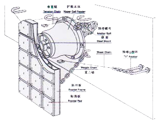
Selecting the Chains
A common fender system with frontal frame usually involve a Weight Chain, Tension Chain and Shear Chain.
Chain
Function
Weight Chain
Normally installed at a static angle of 15 – 25° to the vertical, its main function is to sustain the weight of the entire frame panel structure
Tension Chain
Protect the fender against damage when compressed
Shear Chain
Fixed at 20 – 30° to the horizontal, shear chain exists to avoid damage while the fender is in shear deformation
Some installation do not involve shear chain, but a fender system would definitely be more resistant to shear damage with them.
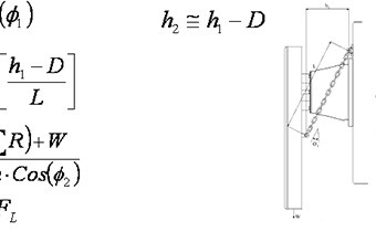
h1: Static offset between brackets(m, ft)
Ф2: Dynamic Angle of Chain(°)
h2: Dynamic offset between brackets at F(m, ft) D: Fender compression(m, ft) R: Reaction Force of rubber units behind the frontal panel(N, Lbs) W: Weight of the panel face(N, Lbs) FL: Safe working Load of chain(N, Lbs) L: Bearing length of chain(m, ft) n: number of chains acting together μ: Friction coefficient of face pad. Usually equals 0.15 for UHMW-PE facings. FM: Minimum Breaking Load(N, Lbs) FS: Safety Factor(2~3 times)
Tips on choosing suitable chains:
Chain sizes should be as exact as possible. An overly tight chain or an overly loose chain would fail the system.
Safety factor has to be considered. At least 2 to 3 times of the work load.
Open link type is more preferable.
Installation tips:
One must consider installation during the early design process and not after choosing the fenders and finalising the purchase as the maintenance, wear allowances and protective nets/coatings will affect their useful life.
Chains should not be installed twisted. They might break due to a reduction in load capacity.